Switching light sources on the principle of "approached, turned on - passed, turned off" - this is one of the options for the efficient use of electric energy. The functionality of such a control system is provided by the same traditional devices - switches, but structurally somewhat modernized.
Switching modernization allows you to connect the passage switch from two and three places to control the light source from each individual point. You must admit that such a solution is especially convenient for long rooms, for example, a corridor.
We offer you to understand the principles of connecting a passage switch to two and three control points. The article provides working schemes for organizing light groups, and also describes the features of the implementation of switching projects.
Loop-through switching of light sources
The logic of saving energy spent on light devices or others is explained by simple user actions.
If a light fixture is needed, electricity is supplied to it by simply closing the switch contact. Otherwise, the opposite is true.

Light Source Switch - Interpreted by Electric Slang - Pass-through switch. It provides a fundamentally new approach in terms of the operation of electrical sections of networks intended for the installation of lighting devices (+)
However, suppose that a room (residential or other purpose) is walk-through. Then the user will turn on the light devices at the entrance, but leaving the room through another door, will no longer be able to disconnect the circuit. There is an irrational use of electricity.
But the situation is easy to correct. And the option to connect a pass-through switch from two places in the room for a loop-through circuit will help to do this.

Long corridors of premises for various purposes - potential objects for the installation of control systems for light sources from different places. It is during the operation of such premises that the urgent issue of saving energy
For example, there is a room with a functional purpose - a corridor. It is required to make control of the general group of lamps of this room from two points - at the first (entrance) and at the second (entrance) door.
Light switching from two places
The lighting of the project corridor consists of two light groups, so it is logical in this case to use two two-gang switches for control.
Accordingly, in addition to them, you will need:
- two sockets;
- one junction box;
- three-core cable.
The meter of electrical conductors should be calculated after drawing up the circuit and planning the wiring. It is recommended that you purchase a cable with a small margin.
The control circuit for two light groups through two-gang switches through passage looks like this:

The control circuit of two separate light groups through two-gadget devices: N, L - a classical electric network; RK - distribution box for cabling; L1, L2 - separate light groups; P - jumper; PV1, PV2 - two-key walk-through switches (+)
The phase conductor is fed to the two-gang device PV1. This switch, having a two-key configuration, respectively, has two terminals for common contacts and four terminals for changeover contacts.
On the first device, the common terminals are connected together and a phase conductor is connected to them. The terminal 1 of the changeover contact PV1 is connected by a wire to the terminal 1 of the changeover contact PV2. Accordingly, terminal 2 of PV1 will be connected to terminal 2 of PV2, terminal 3 of PV1 with terminal 3 of PV2, and terminal 4 of PV1 with terminal 4 of PV2.
Two more terminals remain on the second loop-through switch. Both are common, and they are connected according to the principle: each for one light group (L1 and L2) of the lighting system. Already from light groups by outgoing conductors, the circuit closes to the zero bus of the electric network.
However, this is only one of the possible circuit solutions. So, if one light group is used, it is possible to organize a circuit on single-key switches.
Wiring using single-key walk-through switches looks more economical in terms of material consumption. Less wire is required here, since the number of connecting lines is reduced by almost half compared with the previous solution.
But at the same time, the functionality of the lighting system itself is limited.

Schematic solution for one light group using single-key switches: L, N, PE - classic power wiring on three lines; RK - distribution box; L1 - light group; PV1, PV2 - single-key switches (+)
However, for a device in residential premises, this option can be used most often.
What is required for a control system device on single-key switches?
The answer is obvious:
- single-key switches (2 pcs.);
- Sockets (2 pcs.);
- junction box (1 pc.);
- three-core electric cable (meter size according to calculation).
System requirements are standard. Before the start of work, a scheme is drawn up. Necessary accessories, materials, fasteners are purchased. At the designated places, the socket boxes and the distribution box are installed.

An example of a wiring device for a residential building from the category of standard projects. Two single-key switches are used. The solution was implemented taking into account the wiring of the cable with the ground conductor (PE). This option corresponds to the circuit shown above.
Then the cable is routed and the passage switches from two places are connected to the light source through the junction box.
Phase conductor lead to the common terminal PV2, and the common terminal PV1 output to one contact of the light group. The second contact of the light group is connected to the zero bus, and the changeover contacts of both switches commute with each other, observing the same numbering (1 with 1, 2 with 2).
Three point management solution
The organization of loop switching systems is largely determined by the area of the premises (length), the number of moves (doors). Therefore, the use of circuits with passage switches from three control places or more is not ruled out.
The construction of such schemes, as a rule, is carried out with the participation of the so-called crossover switch.
This is the same switch, but according to the circuit design is made on five contact terminals, two of which are shorted by a jumper. The switching group of such a switch contains four pads.

A widespread version of the circuit design for residential buildings: N, L - household network; RK - distribution box; L1 - light group; PV1, PV2 - feed-through switches; PRK - cross switch (+)
The cross-line switching device is an additional element of the circuit, where it is also supposed to install two walk-through switches.
Simple single-key devices are used.
The principle of operation of the triple scheme is as follows:
- A phase is connected to the “common” terminal of PV1.
- From the terminals of the changeover contacts are connected 1 and 2 contacts of the crossover switch.
- From 3 and 4 terminals of the cross-over switch, connection to 1 and 2 terminals of the change-over contacts of PV2.
- The common terminal “common” PV2 is connected to one terminal of the light group.
- The second terminal of the light group is switched to electric zero.
Such solutions involving exactly simple single-key devices are recommended for use in rooms where the number of inputs / outputs is equal to the number of control places.

The implementation of the circuit solution according to Fig. 6 in its "natural" form. This is what the completed installation indoors looks like, where a control system of three places is needed
For example, to create a similar scheme under the conditions of the passage of a long corridor, for 1 input and 1 output, with switching in the central zone, is clearly impractical. Obviously, it makes no sense to turn off the lights when a person has passed only the first half of the corridor. Meanwhile, in the network you can find similar recommendations of "professional" electricians.
Schemes with control from more than three places
The number of control places, in principle, is not limited. Another question is how difficult such decisions are. The more devices involved in the implementation of the control system, the more complicated the construction scheme.
The number of switched lines, contact terminals is increasing. Accordingly, the cost of components and installation increases. However, projects with 4-5 control points are used quite actively. For example, such a project:

Circuitry for projects requiring an increase in the number of management seats by more than three. In this case, an option for four control points (+)
It uses a pair of single-key simple switches of continuous operation and a pair of switches with a reverse switching function. The diagram shows only one light group. Meanwhile, it is possible to connect additional light groups.
Additional light groups
Additional light sources (light groups) can be switched off via free terminals and act as light sources of intermediate transition zones. That is, in the same long corridors, it becomes possible to use the scheme for a larger number of control places.

Five-point control circuit of the light switching system: L1 - light group; N, L is the network; On 1, On 2 - walk-through switches; On 3, On 4, On 5 - reversible switches (+)
In this case, light groups should be divided into zones of action - input, intermediate, output. With such a decision, it is already possible to pass a long corridor halfway, turn off the lighting on the passed half, and turn on the light on the remaining half.
Multi-element schemes, of course, are of little use for a residential private sector, since projects of this kind rarely have long corridors or rooms of significant area with several doors. But for the commercial sector or the production environment, solutions of this kind are in demand.
The principles of the control system
Mounting features for installing walk-through switches, in general, do not exist. All installation work is carried out as standard, in accordance with the rules for installing ordinary switching devices.

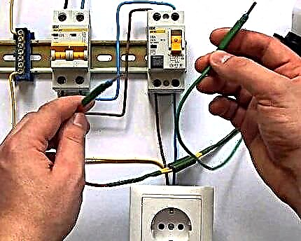
Classical installation detail for wiring inside walls. It is installed (tightly walled up) the socket. An electric cable is output inside the socket. The control device is connected (two-key)
If the budget allows, it is advisable to equip each individual device with a junction box. Then you need to purchase boxes of small size by the number of mounted switches. But the variant with one RK is not excluded either.
The selection factors here are directly related to the specific installation conditions. Usually, the switches flush the wall surface — an internal wiring diagram.
Meanwhile, the implementation of projects for private estates (suburban) often takes place with the installation of schemes of "overhead" (surface) installation, despite the fact that this approach is considered to be obsolete.
For the first case, installation will require socket boxes. For the second - overhead plates. These accessories are necessary to securely fasten the switches in the niches of the wall panels or directly on the walls.

The cable is disconnected strictly according to the diagram indicated on the rear side of the device. The layout of a single-key switch is simple. However, the mismatch of the conductors in case of improper wiring threatens to damage the device
Three-core cables, as a rule, act as an electrical conductor, where two conductors are needed to power the system, and the third is used as a protective grounding circuit.
Household fixtures can be used without “ground” if the case is non-metallic. Industrial lamps must have a grounding bar.
Of course, regardless of the destination, domestic or industrial, the installed network is always connected through additional protection - a circuit breaker. This device is necessarily calculated by the power and cutoff current in relation to the built-in system of continuous light control.
The features of connecting a two-key passage switch are described in this article.
You can find out how the use of circuits for connecting pass-through switches from several places can be found in the videos presented.
The order of connecting the cores in the junction box:
Instructions for connecting from 2 places:
Analysis of possible errors:
The appearance and introduction of devices of this kind in electrical networks may not be so significant, but still affected the ease of use. Moreover, solutions based on switch-through switches actually lead to energy savings.
Meanwhile, the improvement of devices does not stop. New developments periodically appear, for example, similar to touch switches.
Is there anything to supplement, or have questions about connecting a pass-through switch? You can leave comments on the publication, participate in discussions and share your own experience in arranging the power grid. The contact form is located in the lower block.